- 您现在的位置:买卖IC网 > Sheet目录1227 > MA320002 (Microchip Technology)MODULE PLUG-IN PIC32 USB OTG
�� �
�
�PIC32MX3XX/4XX�
�2.5� ICSP� Pins�
�The� PGECx� and� PGEDx� pins� are� used� for� In-Circuit�
�Serial� Programming?� (ICSP?)� and� debugging� pur-�
�poses.� It� is� recommended� to� keep� the� trace� length�
�between� the� ICSP� connector� and� the� ICSP� pins� on� the�
�device� as� short� as� possible.� If� the� ICSP� connector� is�
�expected� to� experience� an� ESD� event,� a� series� resistor�
�is� recommended,� with� the� value� in� the� range� of� a� few�
�tens� of� Ohms,� not� to� exceed� 100� Ohms.�
�Pull-up� resistors,� series� diodes� and� capacitors� on� the�
�PGECx� and� PGEDx� pins� are� not� recommended� as� they�
�will� interfere� with� the� programmer/debugger� communi-�
�cations� to� the� device.� If� such� discrete� components� are�
�an� application� requirement,� they� should� be� removed�
�from� the� circuit� during� programming� and� debugging.�
�Alternately,� refer� to� the� AC/DC� characteristics� and� tim-�
�ing� requirements� information� in� the� respective� device�
�Flash� programming� specification� for� information� on�
�capacitive� loading� limits� and� pin� input� voltage� high� (V� IH� )�
�and� input� low� (V� IL� )� requirements.�
�Pull-up� resistors,� series� diodes� and� capacitors� on� the�
�TMS,� TDO,� TDI� and� TCK� pins� are� not� recommended�
�as� they� will� interfere� with� the� programmer/debugger�
�communications� to� the� device.� If� such� discrete� compo-�
�nents� are� an� application� requirement,� they� should� be�
�removed� from� the� circuit� during� programming� and�
�debugging.� Alternately,� refer� to� the� AC/DC� characteris-�
�tics� and� timing� requirements� information� in� the� respec-�
�tive� device� Flash� programming� specification� for�
�information� on� capacitive� loading� limits� and� pin� input�
�voltage� high� (V� IH� )� and� input� low� (V� IL� )� requirements.�
�2.7� Trace�
�The� trace� pins� can� be� connected� to� a� hardware-trace-�
�enabled� programmer� to� provide� a� compress� real� time�
�instruction� trace.� When� used� for� trace� the� TRD3,�
�TRD2,� TRD1,� TRD0� and� TRCLK� pins� should� be� dedi-�
�cated� for� this� use.� The� trace� hardware� requires� a� 22�
�Ohm� series� resistor� between� the� trace� pins� and� the�
�trace� connector.�
�Ensure� that� the� “Communication� Channel� Select”� (i.e.,�
�PGECx/PGEDx� pins)� programmed� into� the� device�
�2.8�
�External� Oscillator� Pins�
�matches� the� physical� connections� for� the� ICSP� to�
�MPLAB� ?� ICD� 2,� MPLAB� ICD� 3� or� MPLAB� REAL� ICE?.�
�For� more� information� on� ICD� 2,� ICD� 3� and� REAL� ICE�
�connection� requirements,� refer� to� the� following�
�documents� that� are� available� on� the� Microchip� website.�
�?� “MPLAB� ?� ICD� 2� In-Circuit� Debugger� User� ’s�
�Guide”� DS51331�
�?� “Using� MPLAB� ?� ICD� 2”� (poster)� DS51265�
�?� “MPLAB� ?� ICD� 2� Design� Advisory”� DS51566�
�?� “Using� MPLAB� ?� ICD� 3”� (poster)� DS51765�
�?� “MPLAB� ?� ICD� 3� Design� Advisory”� DS51764�
�?� “MPLAB� ?� REAL� ICE?� In-Circuit� Debugger�
�User� ’s� Guide”� DS51616�
�?� “Using� MPLAB� ?� REAL� ICE?”� (poster)� DS51749�
�Many� MCUs� have� options� for� at� least� two� oscillators:� a�
�high-frequency� primary� oscillator� and� a� low-frequency�
��Configuration”� for� details).�
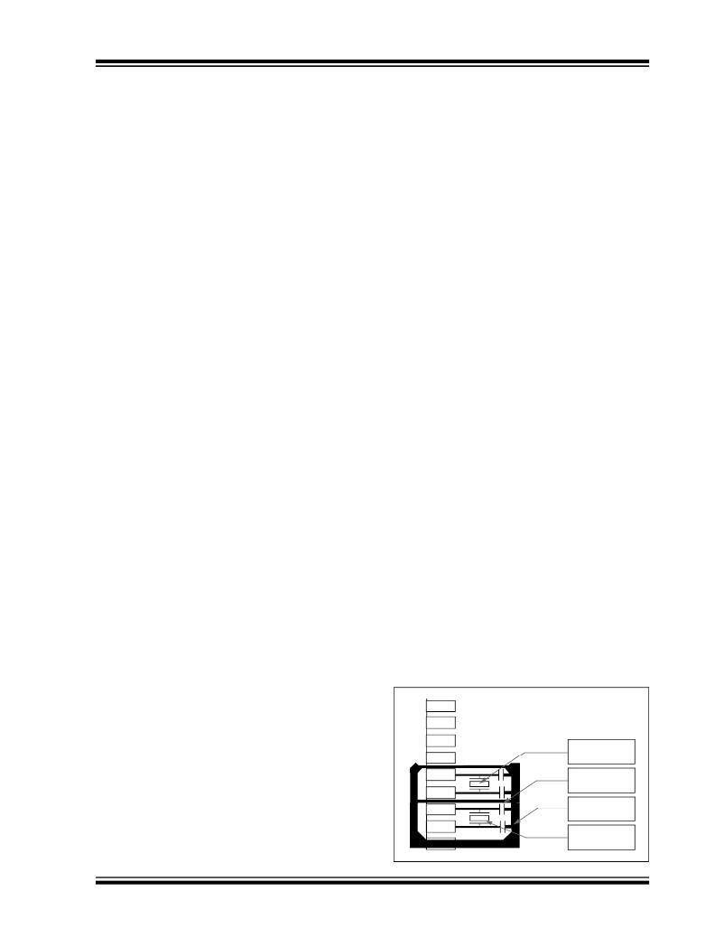
�The� oscillator� circuit� should� be� placed� on� the� same�
�side� of� the� board� as� the� device.� Also,� place� the�
�oscillator� circuit� close� to� the� respective� oscillator� pins,�
�not� exceeding� one-half� inch� (12� mm)� distance�
�between� them.� The� load� capacitors� should� be� placed�
�next� to� the� oscillator� itself,� on� the� same� side� of� the�
�board.� Use� a� grounded� copper� pour� around� the�
�oscillator� circuit� to� isolate� them� from� surrounding�
�circuits.� The� grounded� copper� pour� should� be� routed�
�directly� to� the� MCU� ground.� Do� not� run� any� signal�
�traces� or� power� traces� inside� the� ground� pour.� Also,� if�
�using� a� two-sided� board,� avoid� any� traces� on� the�
�2.6�
�JTAG�
�other� side� of� the� board� where� the� crystal� is� placed.� A�
��The� TMS,� TDO,� TDI� and� TCK� pins� are� used� for� testing�
�and� debugging� according� to� the� Joint� Test� Action�
�Group� (JTAG)� standard.� It� is� recommended� to� keep� the�
�trace� length� between� the� JTAG� connector� and� the�
�JTAG� pins� on� the� device� as� short� as� possible.� If� the�
�JTAG� connector� is� expected� to� experience� an� ESD�
�event,� a� series� resistor� is� recommended,� with� the� value�
�in� the� range� of� a� few� tens� of� Ohms,� not� to� exceed� 100�
�Ohms.�
�?� 2010� Microchip� Technology� Inc.�
�FIGURE� 2-3:�
�SUGGESTED� PLACEMENT�
�OF� THE� OSCILLATOR�
�CIRCUIT�
�Oscillator�
�Secondary�
�Guard� Trace�
�Guard� Ring�
�Main� Oscillator�
�DS61143G-page� 33�
�发布紧急采购,3分钟左右您将得到回复。
相关PDF资料
MA320011
MODULE PLUG-IN PIC32MX220F32D
MA330024
MODULE PLUG-IN DSPIC33F 100TQFP
MA330027
MODULE PLUG-IN DSPIC33F 100TQFP
MA330029
MODULE PLUG-IN DSPIC33FJ16GP102
MA9D00-42
DSUB CONN W/DIAGNOSTIC PORT STRT
MAI
ADAPTER PUSH-ON/M-SWTCH ATTCHMNT
MAV0020RP
VARISTOR ARRY 2ELEMENT 120V 0405
MAX11503EVKIT+
KIT EVAL FOR MAX11503
相关代理商/技术参数
MA320002-2
制造商:Microchip Technology Inc 功能描述: 制造商:Microchip Technology Inc 功能描述:PIC32MX4XX 100 TO 100-PIN USB PIM - Boxed Product (Development Kits) 制造商:Microchip Technology Inc 功能描述:MODULE PLUG-IN PIC32MX4XX 制造商:Microchip Technology Inc 功能描述:PIC32MX4 100PIN USB PLUG IN 制造商:Microchip Technology Inc 功能描述:PIC32MX450 100 Pin to 100 Pin USB Plug in Module 制造商:Microchip Technology Inc 功能描述:Daughter Cards & OEM Boards PIC32 MX450 100-Pin USB PIM 制造商:Microchip Technology Inc 功能描述:PIC32MX4xx 100 to 100-Pin USB PIM, Plug-in Modules
MA320003
功能描述:子卡和OEM板 PIC32MX USB/CAN PIM RoHS:否 制造商:BeagleBoard by CircuitCo 产品:BeagleBone LCD4 Boards 用于:BeagleBone - BB-Bone - Open Source Development Kit
MA320011
功能描述:子卡和OEM板 PIC32MX250F128D PIM
RoHS:否 制造商:BeagleBoard by CircuitCo 产品:BeagleBone LCD4 Boards 用于:BeagleBone - BB-Bone - Open Source Development Kit
MA320012
制造商:Microchip Technology Inc 功能描述:PIC32MZ2048EC 100-100PIN PIM - Boxed Product (Development Kits) 制造商:Microchip Technology Inc 功能描述:MOD PIM PIC32MZ2048EC 100PIN 制造商:Microchip Technology Inc 功能描述:100 to 100 Pin Plug-In Module for PIC32MZ EC Series 制造商:Microchip Technology Inc 功能描述:PIC32MZ2048EC 100-100pin PIM - demonstrate the capabilities of the PIC32MZ EC fa
MA3200-H
制造商:PANASONIC 制造商全称:Panasonic Semiconductor 功能描述:Silicon planar type
MA3200-L
制造商:PANASONIC 制造商全称:Panasonic Semiconductor 功能描述:Silicon planar type
MA3200-M
制造商:PANASONIC 制造商全称:Panasonic Semiconductor 功能描述:Silicon planar type
MA3200W
制造商:PANASONIC 制造商全称:Panasonic Semiconductor 功能描述:Silicon planer type